Building a ’40 Ford Chassis
The hot rod and woodie worlds are circles that intersect. We know a number of guys that have their feet firmly planted in both. It was in the woodie world a few years back that I stumbled across a compete ’40 Ford chassis. By complete I mean it included the engine, trans, rear end, brakes, wheels, tires, gas tank – everything. The old owner wanted a brand new, air-bagged, disc-braked, 350/350 chassis for his car. He didn’t want any of “that old flathead crap.” I saw it as the beginnings of a traditional coupe or roadster build, so I jumped on it.
I have a pair of original Deuce frame rails that these parts will eventually go into, so I put the ’40 frame up for sale. A customer wanted it for his ’40 coupe and let us build it for him. We set it up with split wishbones and a dropped axle, a parallel leaf rear end, and a center cross member modified to accept his modern 350 transmission.
Chassis Engineering (West Branch, Iowa) is the go-to source for the parts needed to convert these frames. CE stuff is well designed, sturdy, and proven. They call their parts “bolt-on” components, but anyone that’s built a car knows what that means. We thought you might like to follow along as we “bolt” this project together.
CE’s dropped axles are forged. I scored one, along with split bones and an unused parallel leaf kit, off the HAMB for the project. We’d already scheduled time at our sandblaster’s for other projects, so we added the ’40 frame and CE parts to the pile and headed down to La Selva Beach to get ’em blasted.


I knew the chassis was square, but until it was blasted and shot with metal-etch primer I didn’t appreciate how cherry it really was. There was almost no pitting from rust and very few kinks. With a little bit of hammer-and-dolly work this chassis could’ve been the foundation for a concours restoration… but we build hot rods…


Rivet-removal was next, and there were a shit-load that needed to come out. Each has to be drilled, chiseled, and pounded — without damaging the original rivet holes (CE uses them to mount their brackets). Some rivets come out easy, some don’t. These were all in the latter category, and nearly four dozen had to go. We cross-braced the frame to keep it square and went to work.
Years ago a big hunk of angle iron had been stick-welded to the rear spreader. It had to go, too. Besides being butt-ugly, it would interfere with CE’s rear spring hangers. We cut it off, revealing a warren of rust and a number of places where the stick weld penetrated the spreader. We welded up the holes, ground it clean, and primered it.


The rear spring hangers went on next. They bolt through the rivet holes we’d opened up, and through new holes we drilled in the vertical wall of the chassis. So far, so good.

The front spring hangers went on next. They require some attention to positioning, and a little more work to mount as the frame rails are double-walled in this location. A Rotabroach was used to drill access holes for these bolts.


We drilled for the rear upper shock mounts and bolted them on, then discovered they needed a bit of persuasion to align with the shocks ends. The lip in the rear cross member also had to be notched to clear the shock tubes.


Once these brackets were in place, we were able to mount the springs, roll the rear end into place, and button it all up. CE’s lower spring plate is designed to accept a sway bar, but the ear is extremely close to the backing plates, so we clearanced and re-contoured it.


Moving forward, Ford employs a heavy-walled “box” to tie together the rails that make up the center X-member. This box is riveted and spot welded, and has to be pounded forward in one piece to come out. To do so, we had to remove the transmission mount and the small cage nuts just behind it. Once gone, we ground off the rust, tacked the cage nut back on, and re-primered.


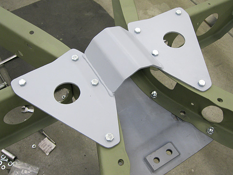
The customer supplied the CE center section kit. Unfortunately, he’d ordered the bottom plate without bungs for attaching the wishbones. We ordered the bungs, reamed them on the lathe for the rod ends, then drilled the plate and welded them in place.


We flipped the chassis right-side-up and began fitting the top plate. Here we ran into issues. As you can see, it only lined up with a few of Henry’s original holes. This wasn’t unexpected, old Ford frames are pretty notorious for their inconsistencies.


We opted to weld up the holes on the CE top plate, then relocate and re-drill them. The result is a plate that drops into place and bolts up squarely and securely, without any unwanted load or torque on the rails.


The last to come out was the original Ford mount for the steering box. CE makes a bracket that mounts to Ford’s original, but it protrudes a bit into the engine bay. Other manufacturers make a bracket that, once the original is removed, mounts the steering box flush with the inside lip of the frame rail. In some cases, this tiny bit of extra clearance is just enough to avoid conflict with an exhaust system.

All done. While this chassis didn’t just “bolt together,” it will now. It can be taken apart, painted or powder-coated, then reassembled knowing that everything will fit.

Comments are closed.

Very nice work! Will be following your build!
http://www.32fordroadster.com
Very nicely done, Dave…it’s amazing how seemingly quality after market parts still need to be modified to fit properly.
Dave –
…more clearly described and shown than R&C, Street Rodder, Hot Rod, or most other
publications. Nice work!